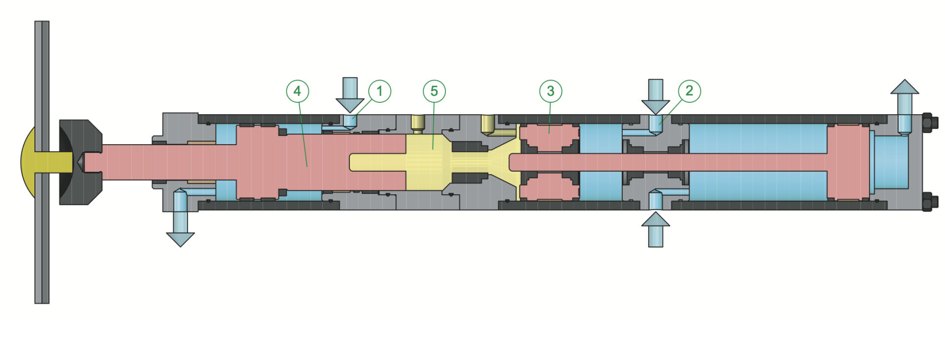
The fast approach run without power
The cylinder is supplied with compressed air at the marks (1) and (2). The rapid but rapid yet controlled descent of the feed piston (3) and the slider (4) takes place until resistance is reached. In this step, the oil fills the hydraulic chamber (5).
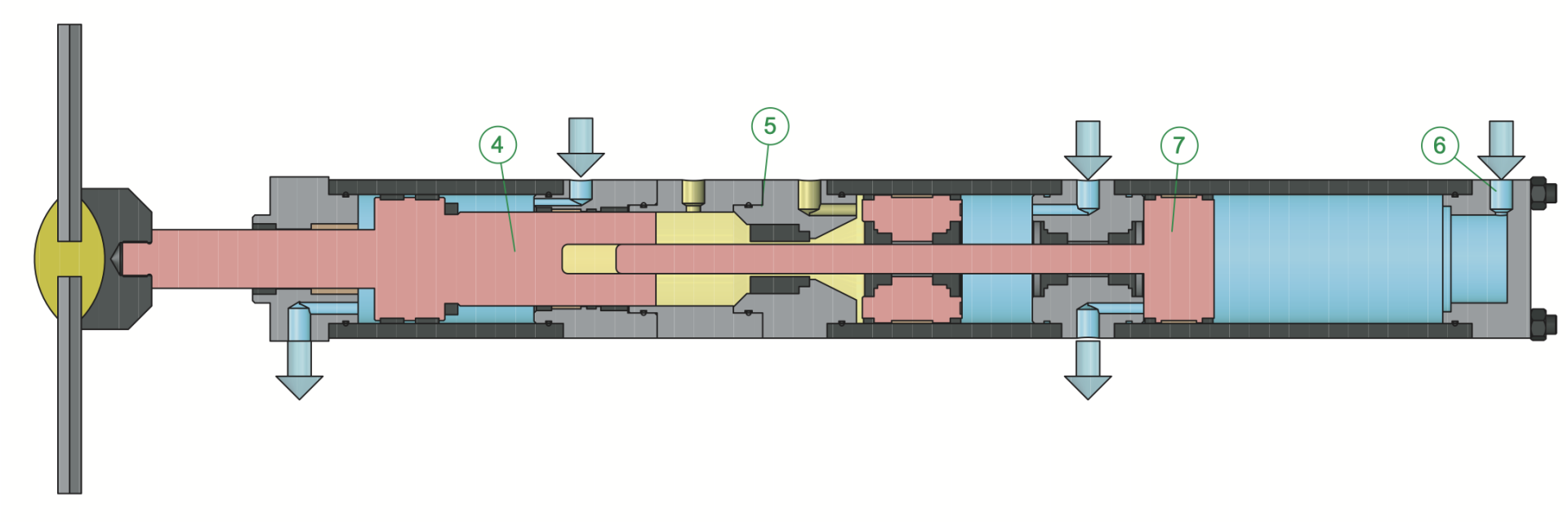
The slow working stroke with power
A control valve switches the pneumatic supply to the mark (6), the working piston (7) descends. During this phase, the plunger rod of the working piston (7) enters in the hydraulic chamber (5), compresses the oil, which greatly increases the power of the slider (4).
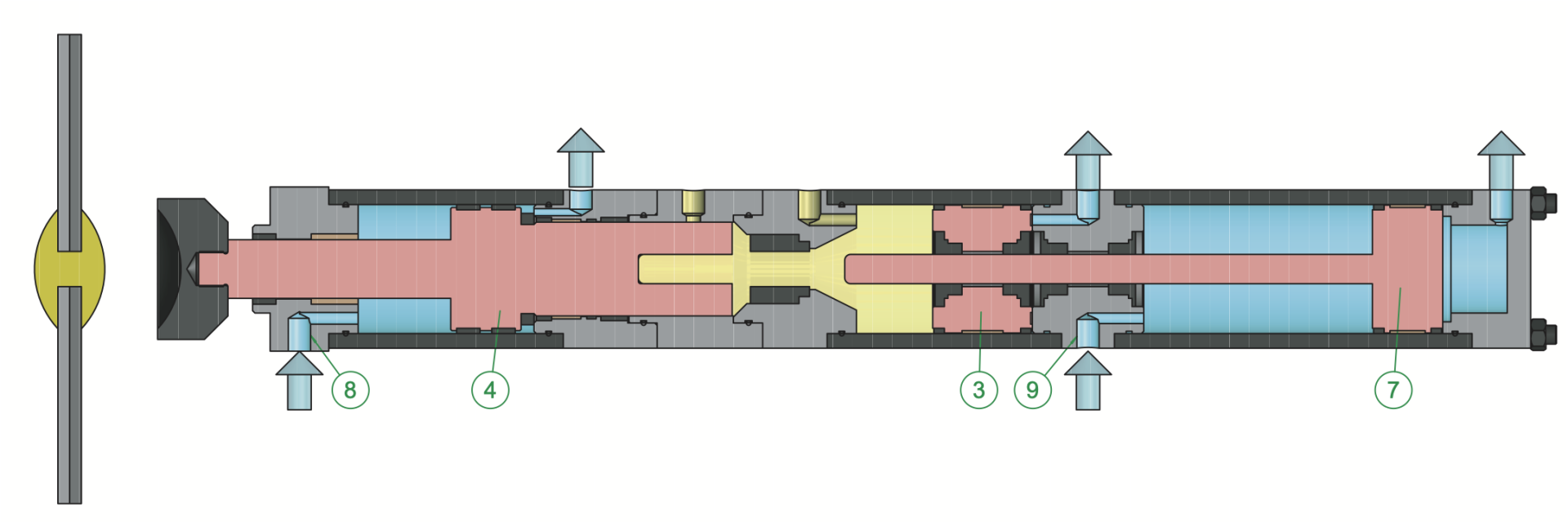
The return stroke and the stand-by position
The cylinder is supplied with compressed air on the marks (8) and (9). The slider (4), the feed piston (3) and the working piston (7) rise at high speed and remain held in the high position.